Phasing Short HF Vertical Antennas
By Glenn McConkey, W8BVI
The technical stuff
I have used short vertical antennas (SVA) since the mid 1970's, and have used the SVA's for short vertical phase arrays (SVPA) for several years with positive results.
The initial 40 meter phased array consists of two 10 foot high elements spaced one-half wave length apart. This array was limited because the bidirectional radiation pattern could only be turned in increments of 90 degrees by changing the phase (0 or 180 degrees) of the RF current between the elements. Adding a third element the bidirectional main lobe and the null can be positioned in increments of 30 degrees.
Photo 1 is the initial two element array with the additional third element. Short vertical elements spaced one-half wavelength apart, avoid any mutual coupling that would change the self resonance impedance of the elements. This is a huge advantage because there is no need to insert networks or other matching devices to compensate for the mutual couple impedance change.
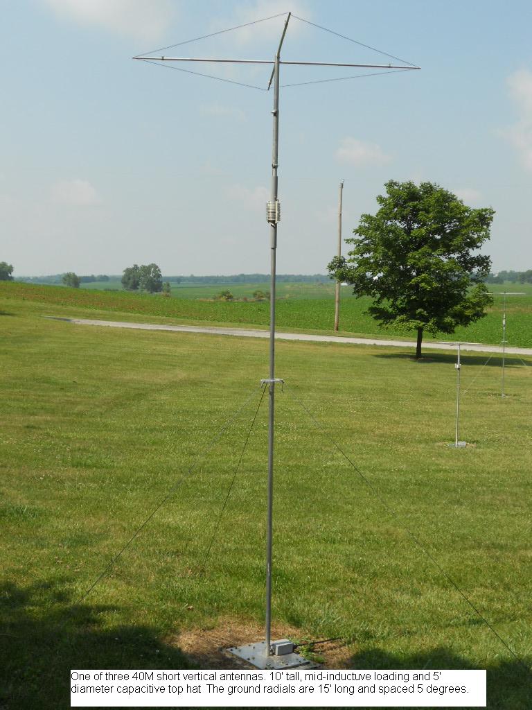
Photo 2 is an example of the SVA for 40 meters. The vertical element is 10 feet high and a 5 foot diameter capacitive top hat is used to increase the base impedance. The base impedance of 12 ohms was achieved by positioning the inductor, used to resonant the antenna on 7.2 MHz, 30 inches below the top hat. A Ruthroff designed high efficient 4:1 coaxial toroid transformer, Photo 3, is installed at the base of the antenna to produce an impedance of 50 ohms at the feed line connection. This high Q antenna has a 2:1 VSWR bandwidth of 50 KHz and return loss is greater than 25 dB, or a VSWR of 1.12:1 at the resonance frequency.
The efficiency of a SVA is reduced primarily due to loss in the coil assembly required to make the antenna resonant. Photo 4 shows an example of two different coils that have been used and evaluated for the 40 meter antenna. Field strength measurements showed the copper coil produced a .2 dB improvement compared to the aluminum coil, but considering the additional cost, weight, and wind loading, the smaller size aluminum coil was chosen.
Maintaining high efficiency of any vertical antenna also requires a counterpoise or a ground radial system. Typically for the installation of a one quarter wavelength vertical element, the ground radials are also one quarter wave in length for maximum efficiency. The installation of a 40 meter vertical with one hundred radials of 34 feet would require 3400 feet of wire. For 5 degree spacing between the radials, 72 radials would be installed and require 2448 feet of wire.
The ground radials for a SVA can be made shorter because the radius of the ground or radial induced currents from the antenna does not extend out as far. For the 40 meter SVA the radials are 15 feet long and the 20 meter SVA radials are 10 feet long. Each antenna has 72 radials for a spacing of 5 degrees. Radiation efficiency of the SVA would improve about .6 dB if 36 additional radials, one quarter wave length long, were installed with the short radial system.
Method I use for the installation of the 72 radials is simple and installation is less than 1 hour. The antenna base assembly consists of two aluminum plates identified as the bottom base plate and the top base plate, shown in Photo 5. Start the installation by positioning the bottom base plate on the ground where the antenna is to be installed.
Plastic 6 inch long tent pegs are one method used to secure the ends of the radials. The 72 pegs are equally spaced and located 15 feet from the center of the antenna for the 40 meter installation. Wire used for the radials is 17 gauge aluminum and is not cut at the ends, but instead is partially wrapped and secured to the back side of the peg. After the wire is secured to the peg it is then connected to the adjacent peg, and then unrolled towards the bottom base plate to the peg on the opposite side. See Photo 6. After completing the installation there will be 36 wires center over the bottom antenna base plate shown in Photo 7.
The top base plate is installed over the bottom base plate, and one-quarter inch diameter hardware is used to compressed the two plates together and provide connection to the radials. This method is simple when compared to the usual method of using a machined plate with drilled and tapped screw holes, and attaching the ends of individual radials using stainless steel hardware.
Photo 8 is the 40 meter SVPA with the addition of the 3 element 20 meter SVPA. Dimension of the 20 meter SVA, shown in Photo 9, is approximately one half the 40 meter antenna, and impedance at the feed line connection is 50 ohms. Mutual coupling is not a problem and the pattern characteristic of this array is the same as the 40 meter array.
Routing and controlling the phase of RF currents to the elements of a SVPA is accomplished by relays located in the antenna phase control unit (APCU), Photo 10. Only two elements are used for phased array operation with the third element connected to ground by the APCU. A one-half wavelength of RG-58A/U coax is used to produce the required 180 degrees difference of RF current between the two one-half wavelength spaced elements for end fire operation. To operate the APCU, a multi-conductor shielded cable is connected between the APCU and the station control unit, shown in Photo 11.
Continuing...
The APCU is located at the center of the array and will require approximately 40 feet of coax to reach the 40 meter elements. It is important that the lines are cut the same length to avoid any phase errors of RF currents to the elements. Differences in the length of the lines and / or incorrect spacing between elements will seriously affect the null in the radiation pattern. Use 100% shielded low loss LMR-400UF coax and install ferrite toroids, shown in Photo 12, to minimize feed line radiation. The same feed lines and APCU can be used for the 20 meter array, but will require changing the length of the 180 degree coaxial delay line.
The impedance at the station feed line connection at the APCU is 50 ohms when feeding one SVA element, or 25 ohms when feeding two SVA elements for phase array operation. A 2:1 ratio Ruthroff designed RF transformer, shown in Photo 13, is installed between the APCU and the station feed line, shown in Photo 14, for impedance matching. A DPDT relay, controlled by DC voltage on the feed line, is used to by pass the transformer when feeding one antenna.
Comparing a vertical antenna to another vertical antenna the radiated pattern difference may be a fraction of a dB. A radio receiver S-meter does not provide the required resolution when comparing vertical antennas. A Hewlett Packard 8569B spectrum analyzer, with dual trace storage and display capability, and .2 dB display resolution, was used for comparing the SVA or SVPA to a reference antenna.
The reference antenna is a Hy-Gain 18HT with 100 ground radials. This 5-band highly efficient no trap vertical antenna is located about 200 feet from the SVPA. The entire 50 foot length of the antenna is used as a 3/4 wavelength element for 20 meters, and stud matching is used to produce a 1/4 wavelength long 40 meter antenna.
Signals from international broadcast stations, amateur SSTV, or other continuous carrier / data modes were fed to the spectrum analyzer to compare antennas. Compared to the 18HT, the SVA received signal was down 1.6 dB on 40 meters, and received signal was down 1 dB on 20 meters. Due to the 3/4 wavelength of the 18HT for 20.meters, take-off angle of radiation is higher producing less gain compared to the 20 meter SVA when receiving signals over 1000 miles away.
Bi-directional major lobe and null radiation pattern of the SVPA was also compared to the SVA and the 18HT. Switching between broadside and end fire radiation the averaged gain of 2.8 dB is shown on the analyzer when comparing the SVPA to the SVA. The SVPA compared to the 18HT showed a averaged gain of 1.2 dB on 40 meters and 1.6 dB on 20 meters. Null measurements of received signals were typically 20 - 30 dB down compared to the major lobe. With RF applied to the array and measuring the radiation pattern at ground level, null measurements were typically greater than 34 dB.
The proper operation of a SVPA is not as simple as a dipole antenna and test equipment is required for the critical adjustment and ops checking the SVA and SVPA.
- Antenna or network analyzer for checking the 2:1 and 4:1 transformers, and to verify each antenna element has the same base input impedance at the same resonant frequency.
- Coaxial current probes and an oscilloscope to measure the amplitude and phase of the current at the base of the antennas. Two identical current probes are manufactured using one-half inch copper pipe fittings, bnc connectors, toroids, and other items shown in Photo 15. The most important features of the scope is the capability for dual trace and the time base of the horizontal sweep to produce a 1 cycle resolution on the screen for measuring the phase difference of the currents. Battery operated unit is ideal.
- RF voltage probe to accurately measure the electrical length of the 180 degree coaxial delay line. The antenna analyzer provides the RF source and frequency and a multimeter or o'scope to measure the voltage. Using the voltage probe is the best method to accurately measure the length of delay lines as explained in the ARRL Antenna Manual.
- Test equipment to measure the radiation pattern of the array. Several options but the best is using a spectrum analyzer.
Several reference books were consulted for this project.
- ARRL Antenna Manual
- Antennas, by John Kruse, W8JK
- Low-Band to DXing, by John Devoldere, ON4UN
- Transmission Line Transformers, by Jerry Sevick, W2FMI
- The Short Vertical Antenna and Ground Radial, by Jerry Sevick, W2FMI
- Reflections, by Walter Maxwell, W2DU
- Antenna Manual, by Woodrow Smith
- Radio Engineering, by Frederick Terman
- Articles from QST, Ham Radio, QEX, and other publications
Information presented shows that the SVA can be an effective, low profile, and low cost antenna that is easy to construct. Spacing SVA's one-half wavelength apart does not produce any mutual coupling between elements. Using SVA's in a phase array will produce some gain and similar radiation pattern produce by one quarter wavelength verticals. Download some jpg drawings of the 20 meter and 40 meter SVA, in a zip file, here.